P186
Half and Full Adders (基本加法器,半加器和全加器)
Adders are important in digital systems in which numerical data are processed.
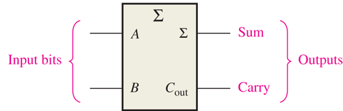
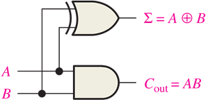
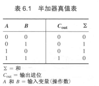
Half-Adder

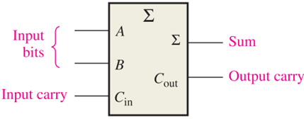
Full-Adder

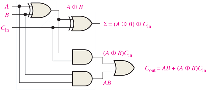
Logic Expression:
四种情况。
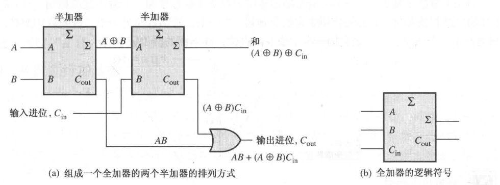
A full-adder can be formed with two half-adders.

进位的逻辑:只要一个半加器有进位,就有进位。因为这是至少有两个输入 了。
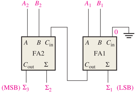
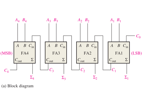
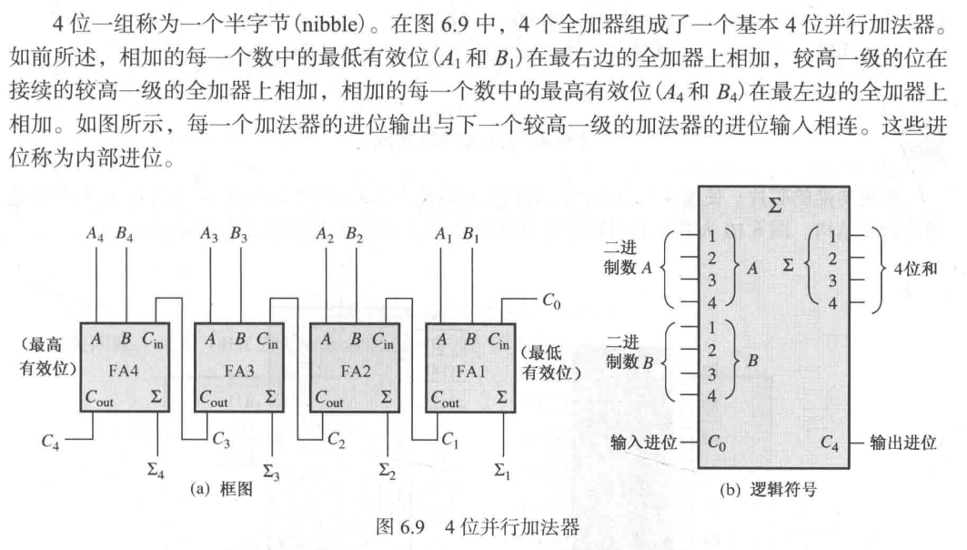
Parallel Binary Adders (并行二进制加法器)
A single full-adder (FA) can add two 1-bit binary numbers and an input carry.
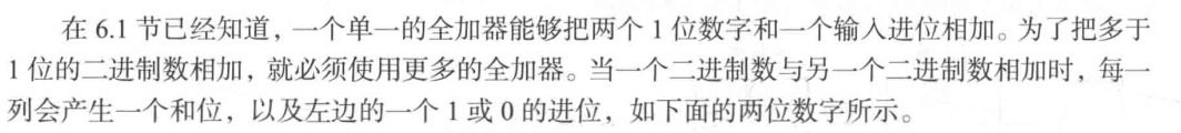
How to add binary numbers of more than one bit?
Recall that binary addition is performed in a bit-by-bit manner.
74LS283
74LS283 is a fixed-function IC for 4-bit parallel adders.
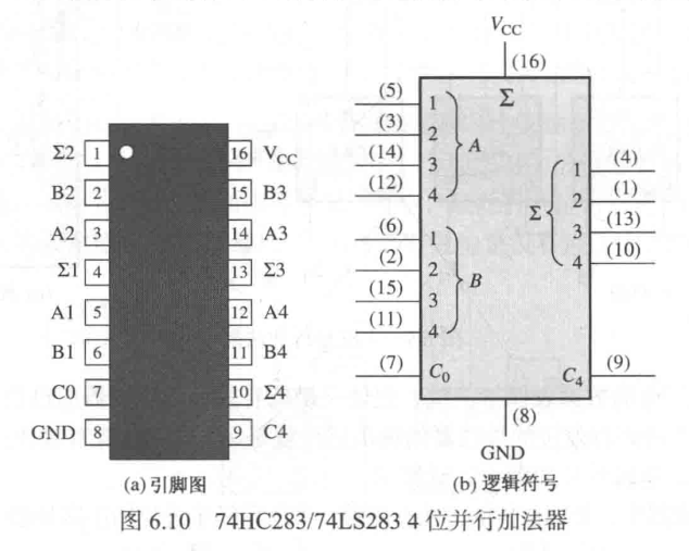
One can cascade (级联) two 4-bit adders to form 8-bit parallel adders.
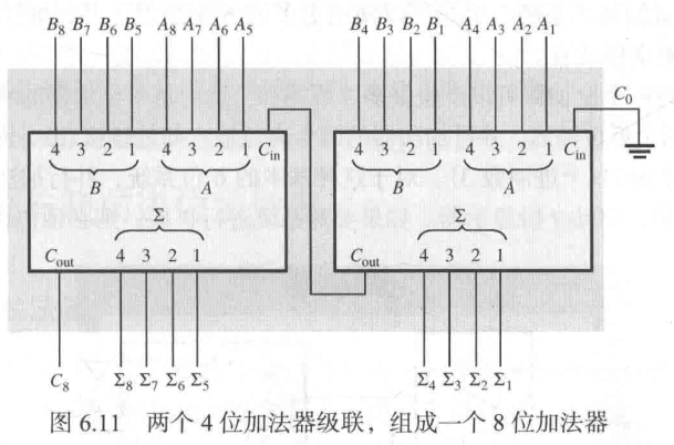
巧妙地利用了全加器的性质。。
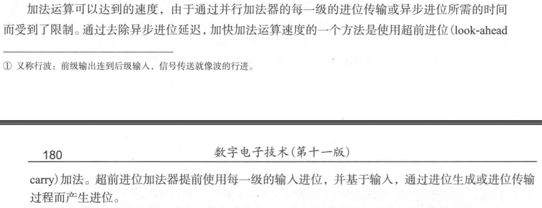
Ripple Carry and Look-Ahead Carry Adders 逐位进位加法器,超前进位加法器
逐位进位(异步,前继输入连到后继输入,信号的传送就像波的前进)加法器,超前进位加法器
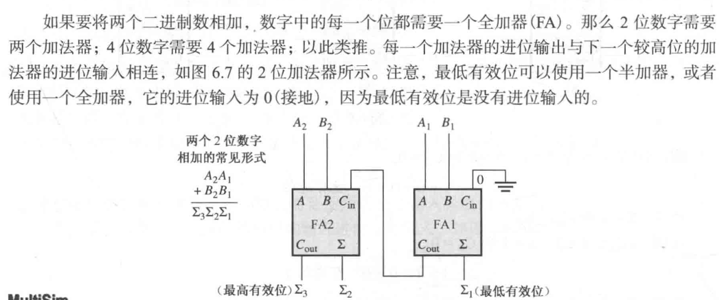
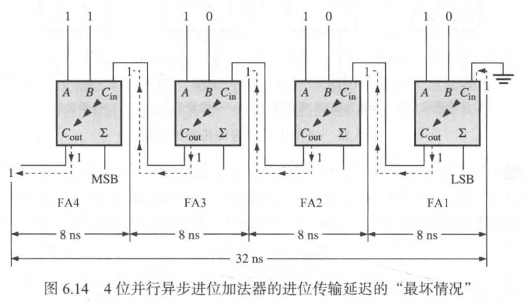
A ripple carry adder is one in which the carry output of each full-adder is connected to the carry input of the next higher-order stage.
Since the output of any stage cannot be produced until the input carry occurs, a carry propagation delay is caused in the addition process.
The Ripple Carry Adder
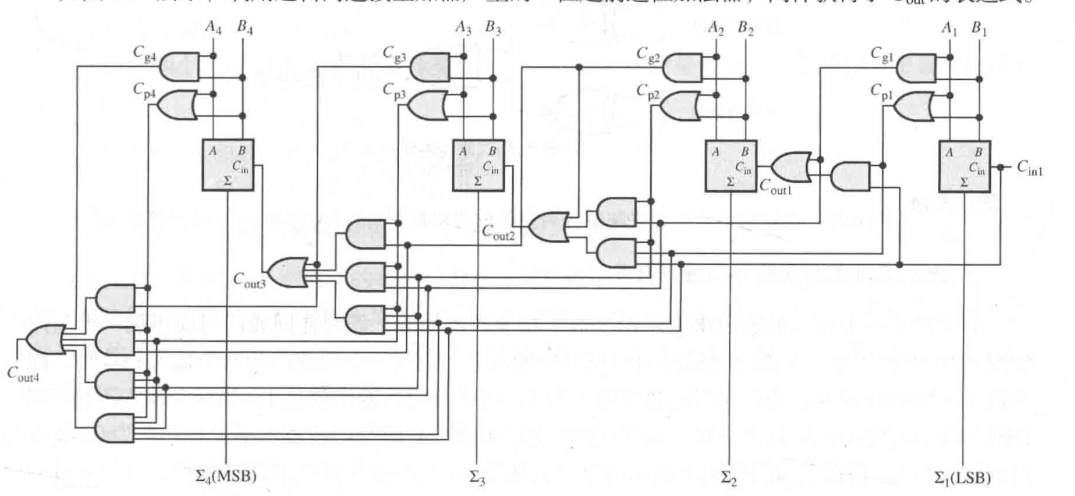
The Look-Ahead Carry Adders
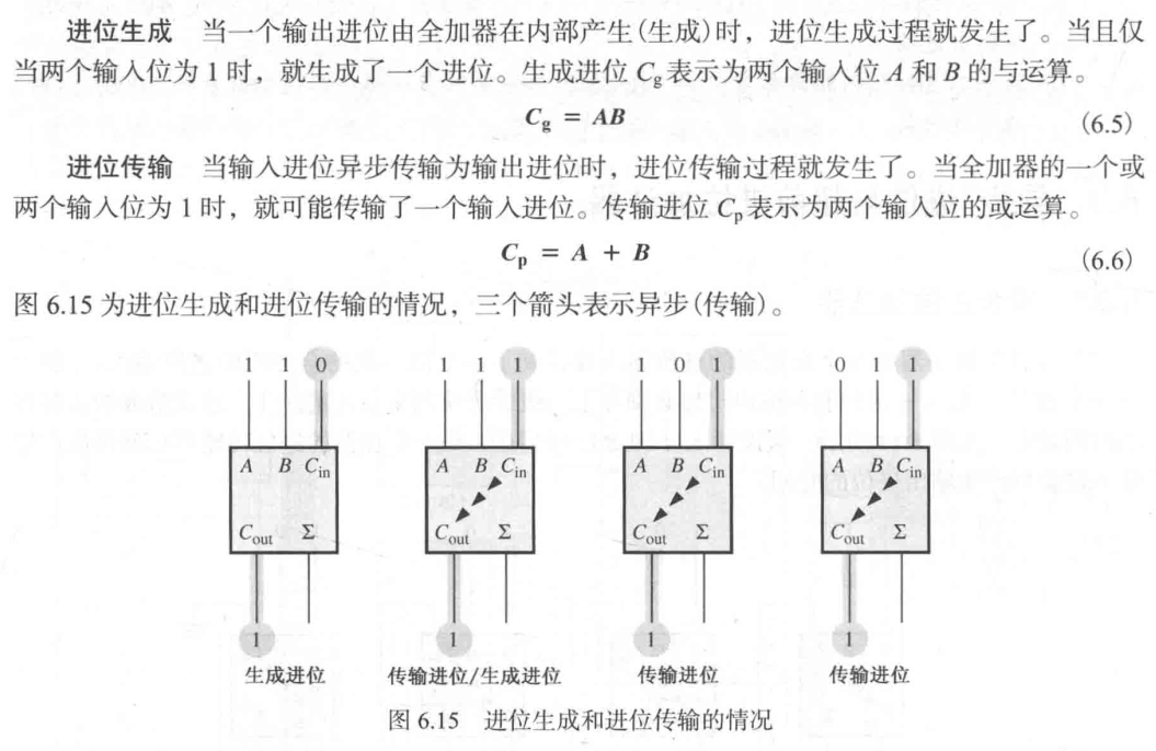
注意这里是一定进位和有可能进位,需要考虑两种 对应的情况。
超前进位,也就是提前判断进位的情况。为什么要判断进位的情况?因为异步加法器的计算瓶颈在于不知道进位的情况。
表示:
- 如果 ,也就是 ,就可以断定一定发生了进位。
- 如果 ,而且 ,代表一定产生了二进制数 ,发生了进位。
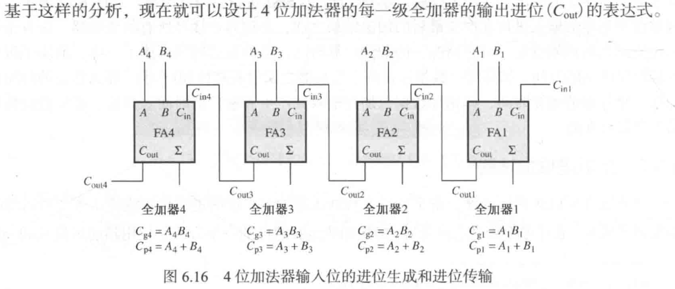
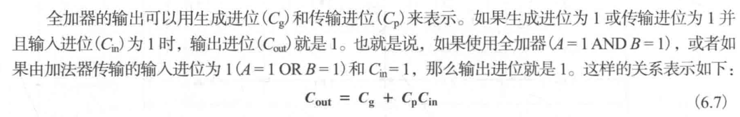
The carry look-ahead adder, based on the input bits of each stage, anticipates and produces the output carry of each FA by.
- Carry generation. .
- Carry propagation: .
利用 ,对式子进行展开。
74LS83A
Except for 74LS283 previously mentioned, 74LS83A is another fixed-function IC of 4-bit parallel adders with lookahead carry. (The pin number of 74LS83A is different from 74LS283).

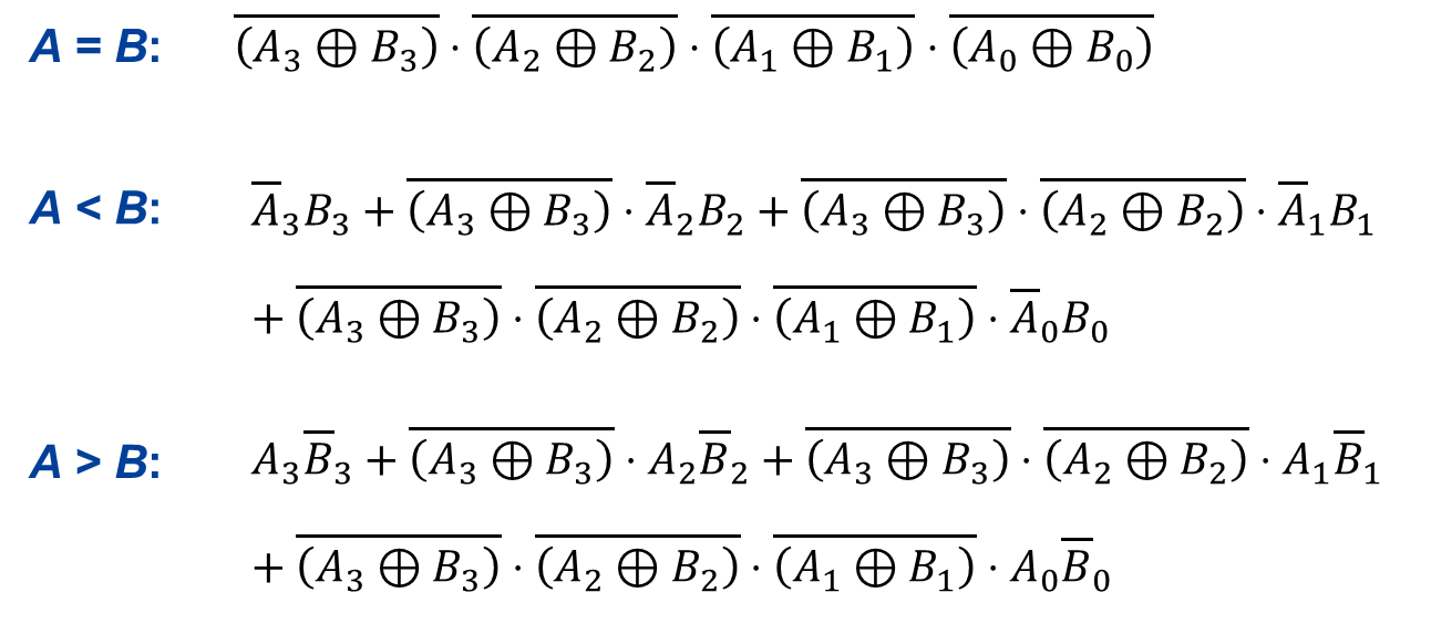
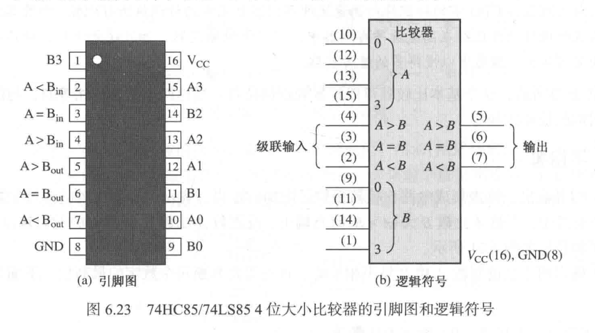
Comparators(比较器)
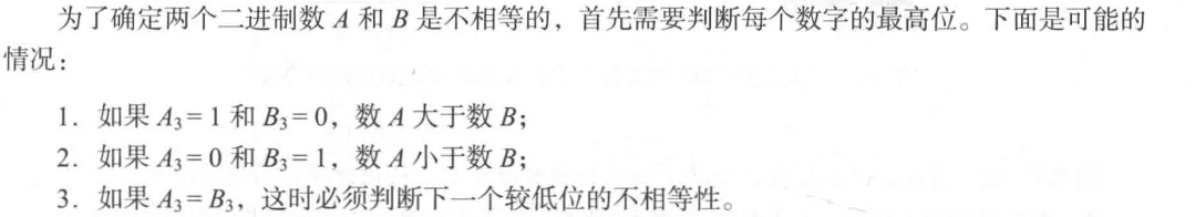
In its simplest form, a comparator determines whether two numbers are equal.
相等 XNOR
if and only if and .
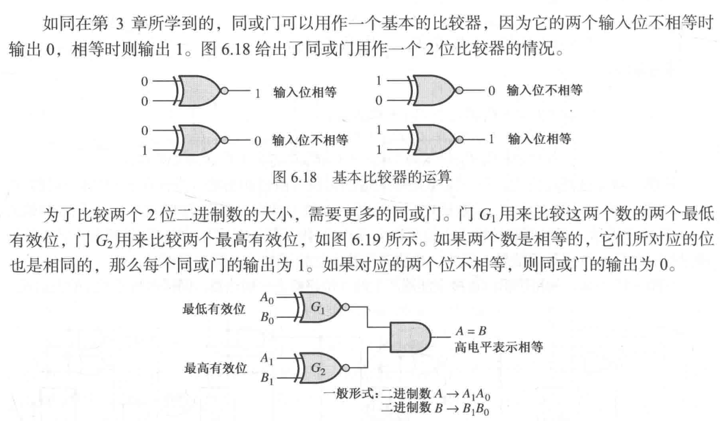
不相等
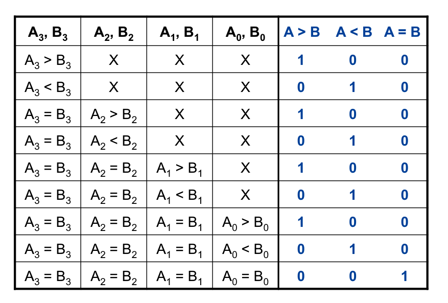
Basic comparing principle:
- Check for an inequality in a bit position, starting with the highest-order bits.
- If higher-order bits are equal, then the result is determined by lower-order bits.
Decoders(译码器)
A decoder is to detect the presence of a specified combination of its input bits (code) and to indicate that code by a specified output level.
A decoder, with input lines to handle input bits, can have output lines, each indicating the presence of one or more -bit codes. 简单记,译码器就是将较少的编码转化为较多的输出。
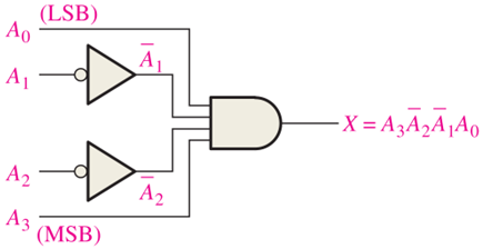
Produce a HIGH output when the input code is 1001. 这是 Decoder 中的一小部分。
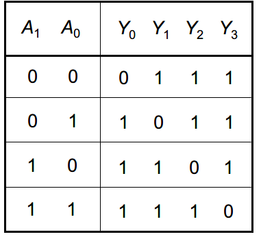
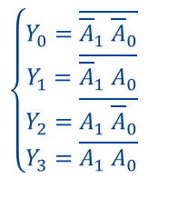
The 2-Bit Decoder
- It is also called a 1-of-4 decoder 会单独出现一个特殊状态 or a 2-line-to-4-line decoder 输入2,输出4.
- “BIN/DEC”: A binary-to-decimal decoder.
- Active-HIGH output: A HIGH output indicates the presence of the code.
- Active-LOW output: A LOW output indicates the presence of the code.
The enable input (EN, 使能端) enable/disable the decoder to accept the input code.
An application of EN is to expand the decoder.
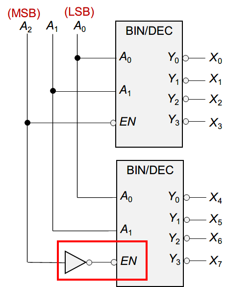
If , then are disabled.
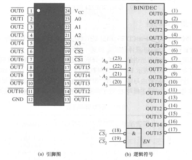
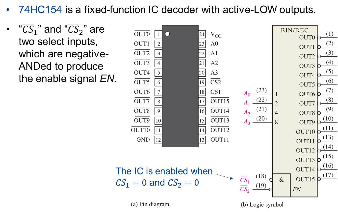
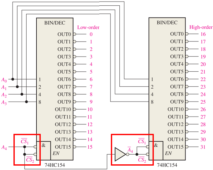
74HC154
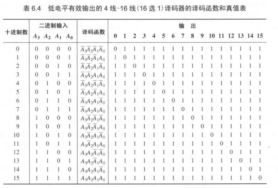
74HC154 is a fixed-function IC decoder with active-LOW outputs.
A 5-bit decoder implemented by two 74HC154s.
The BCD-to-decimal decoder converts each BCD code into one of ten possible decimal digit indications.
It is usually called 4-line-to-10-line decoder or 1-of-10 decoder.
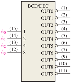
74HC42

注意,输出需要反相。

平时都是高电平,输出 Y 为低电平,如果出现了 1,2,4,7 则 Y 为高电平。
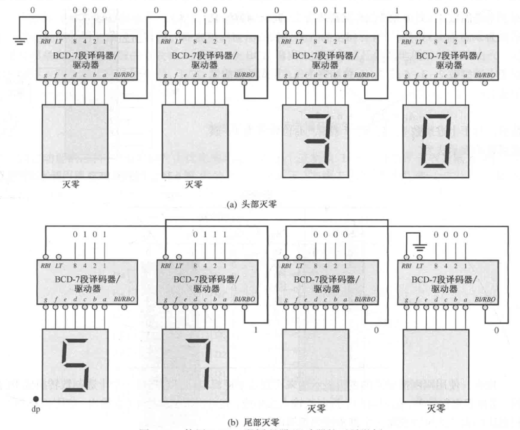
The BCD-to-7-segment decoder converts the BCD code inputs to outputs that drive 7-segment displays.
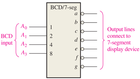
74HC47
74HC47 is a BCD-to-7 segment decoder with active-LOW outputs.


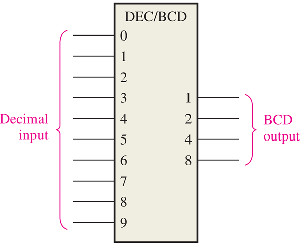
Encoders (编码器)
The process of converting from familiar symbols or numbers to a coded format is called encoding.
An encoder essentially performs a “reverse” decoder.
An encoder accepts an active level on one of its inputs (e.g., a decimal digit) and converts it to a coded output (e.g., BCD).
The decimal-to-BCD priority encoder offers additional flexibility in that, if more than one inputs are active, the encoder will produce a BCD code corresponding to the highest-order decimal digit input that is active and will ignore any other lower-order active inputs.
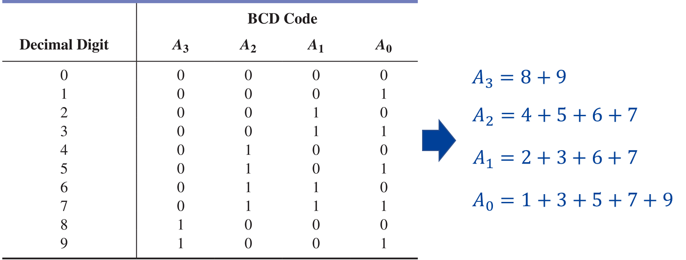
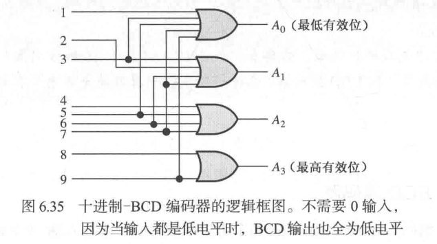
考虑每个输出位。
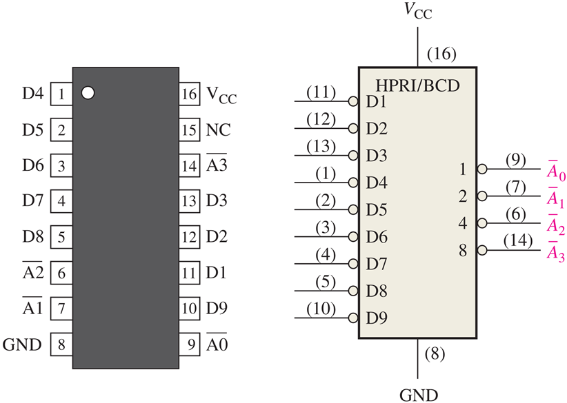
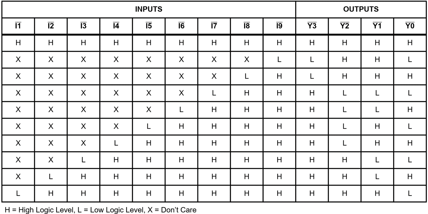
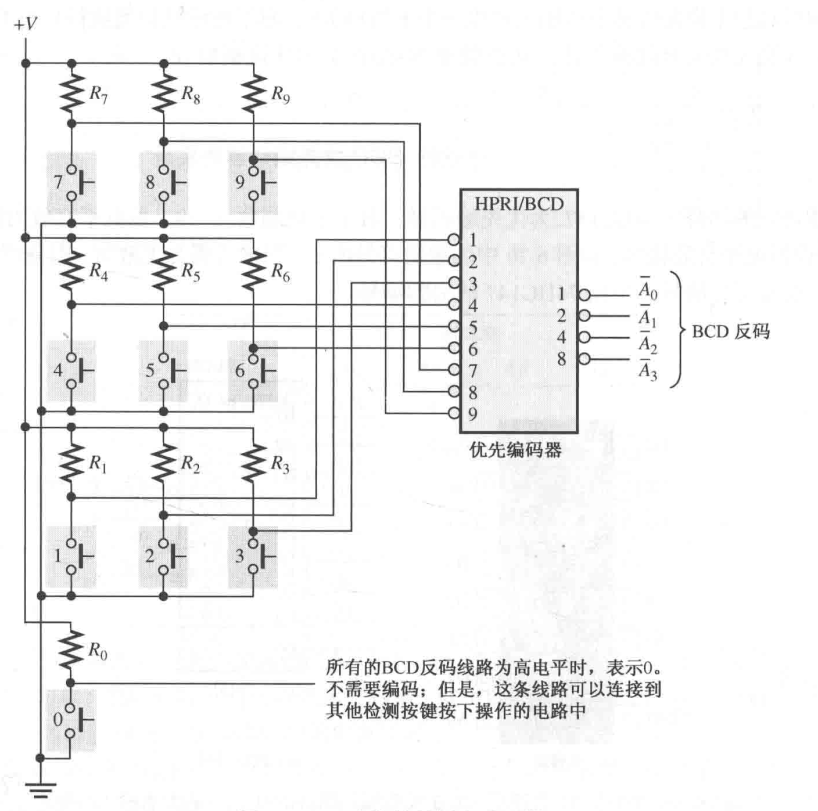
74HC147
74HC147 is a decimal-to-BCD priority encoder with active-LOW inputs and active-LOW outputs. (HPRI means highest value input has priority.)
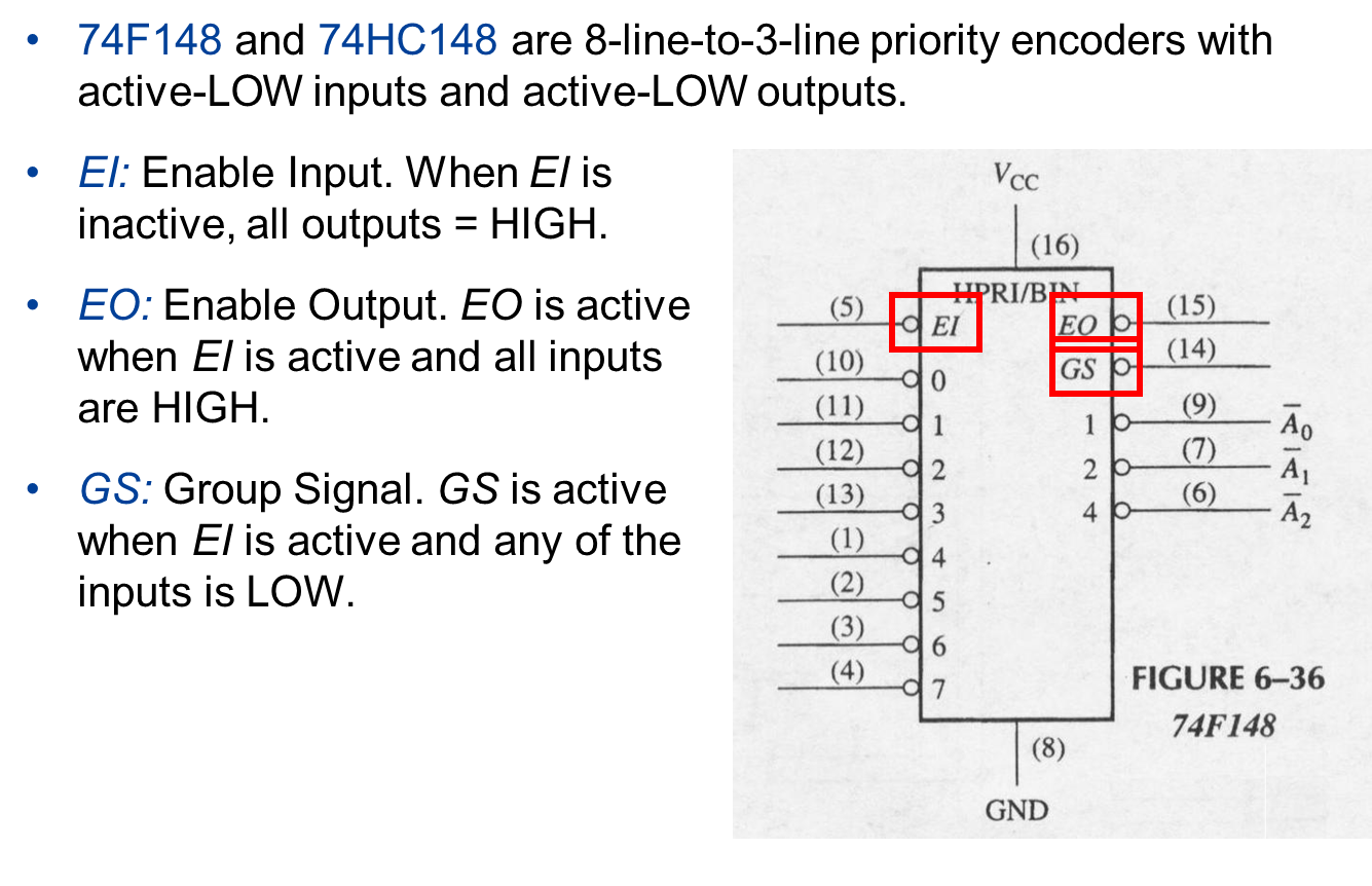
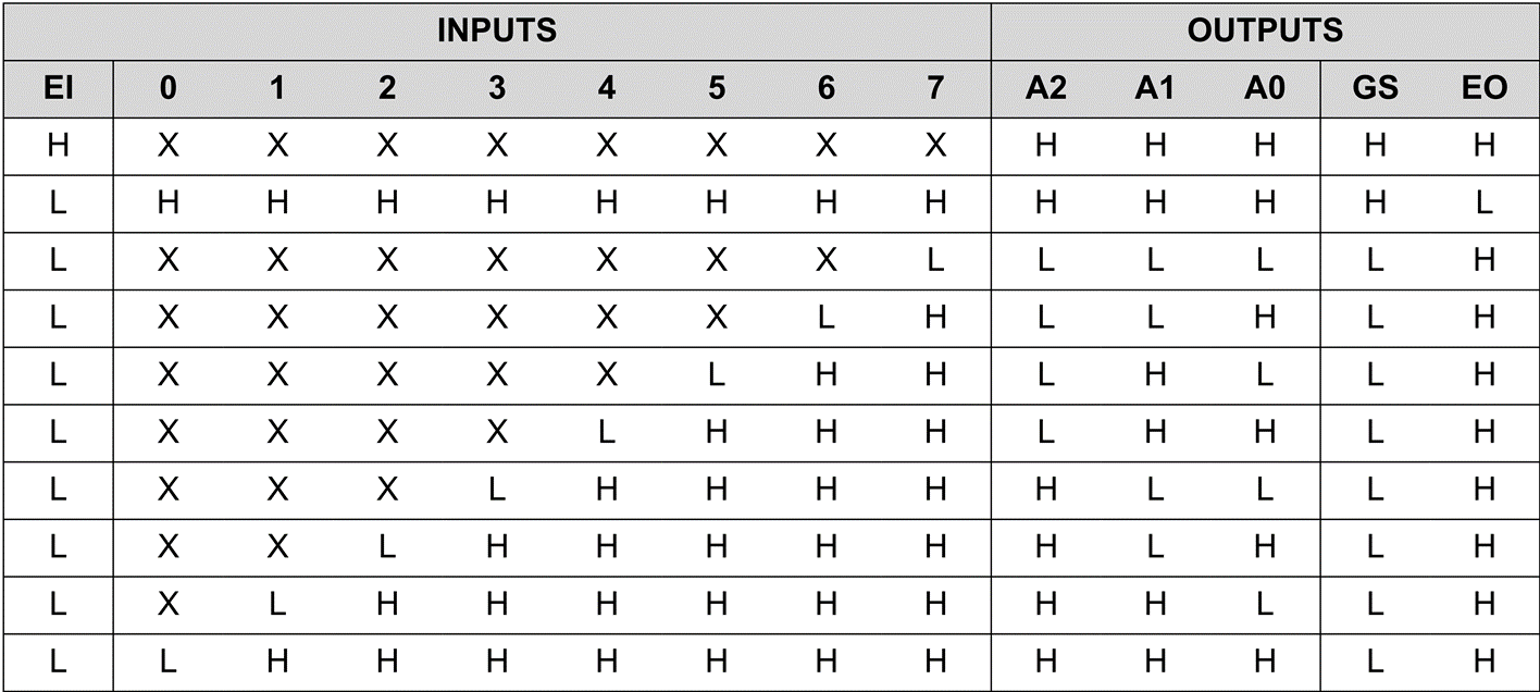
The 8-Line-to-3-Line Priority Encoder
Code Converters (代码转换器)
Conversions between BCD and binary
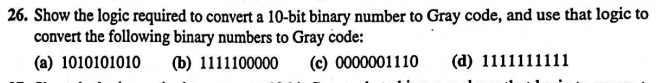
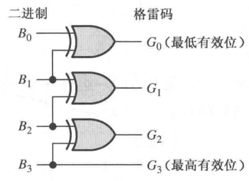
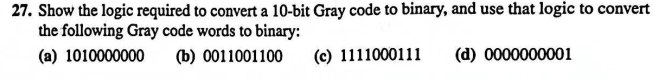
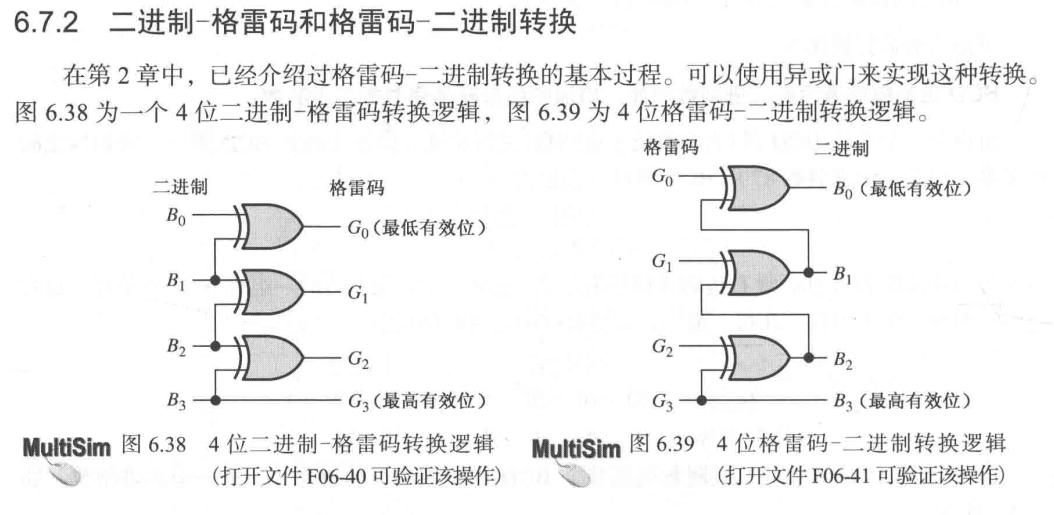
Conversions between Gray and binary

BCD-to-Binary Conversion

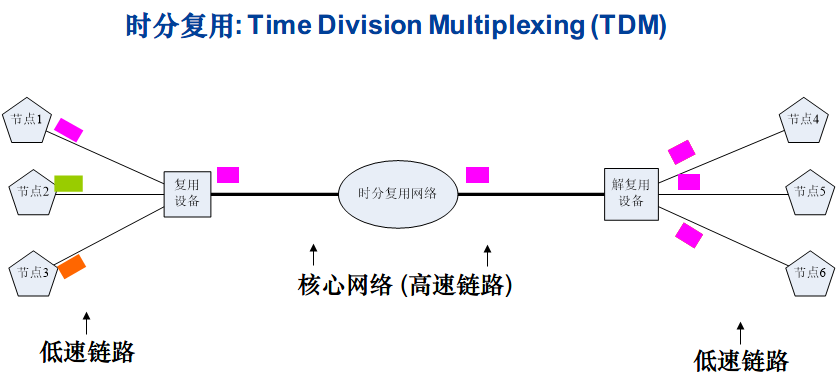
Multiplexers (Data Selectors) (多路复用器、数据选择器)
在一个多路复用器中,数据从几条线路传送到一条线路上。
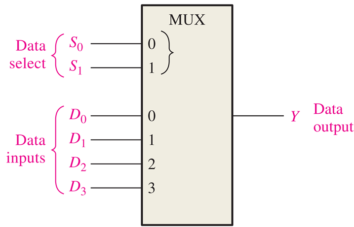
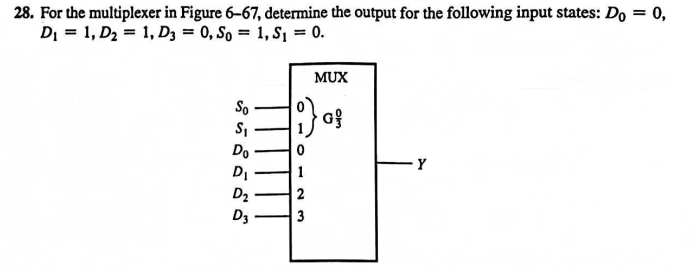
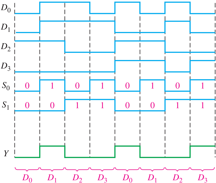
A multiplexer (MUX) is a device that allows data from several sources to be routed onto a single line for transmission over that line to a common destination.
It has multiple data input lines and a single output line. (多输入单输出.)
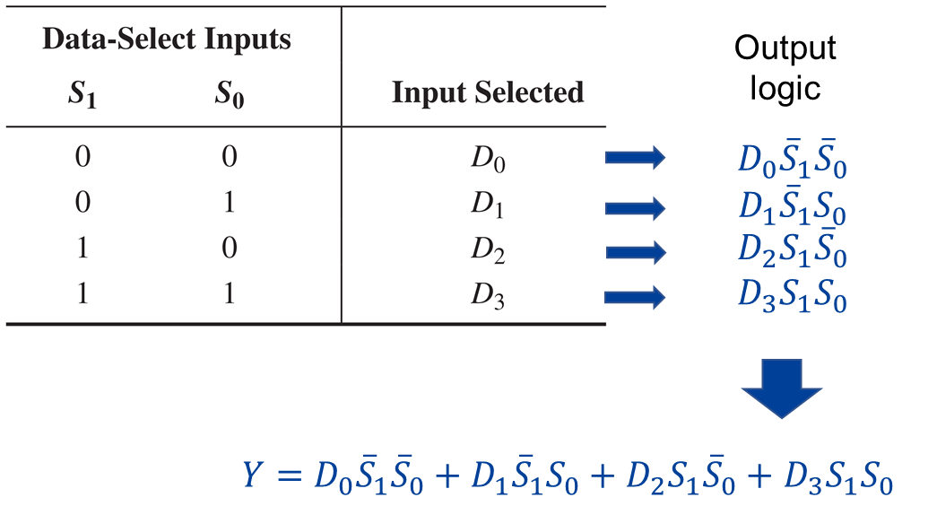
It also has data select inputs (数据选择输入), which permit data on any one of the inputs to be switched to the output line.
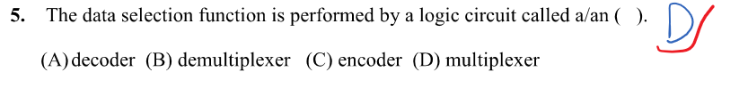
MUX = Data selector (数据选择器)
可以将多条线路的数据转移到一条更加高速的线路。

一般 PIN 安排的方式是 LSB 在上,MSB 在下。
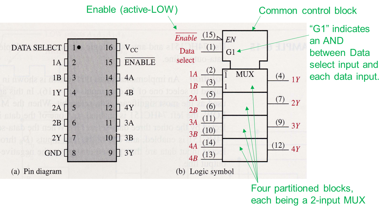
74HC157A


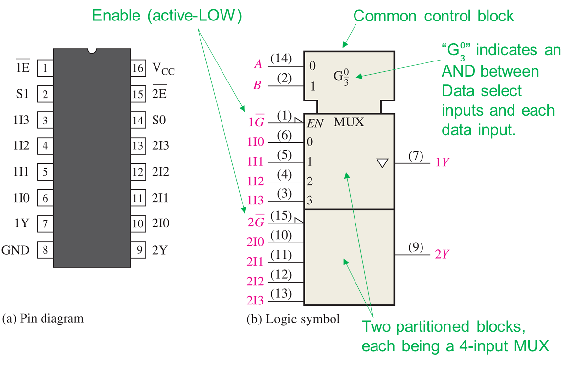
74HC153
74HC151

如果 Enable 施加高电平,则输出 为低电平。

Application: Logic Function Generator
A MUX can be used to implement any combinational logic function in SOP form by connecting the variables to the data select inputs and setting each data input to the logic level required in the truth table for that function.
(数据选择输入 连接到 变量, 数据输入 设置为 真值表对应输出)
Basically, an n-input MUX can implement an n-variable logic function.
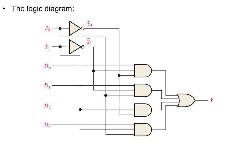
Logic Expression of a 3-input MUX

Using or , we can implement any -variable logic function.


与6.8节内容不一样的地方在于:6.8节说可以实现n+1个变量的逻辑函数,但无需使用除非门以外的其他逻辑门。而这里之所以能处理n+2个变量,是因为使用了非门之外的其他门电路。相应地,可以扩展到更多变量的情形。
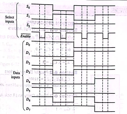
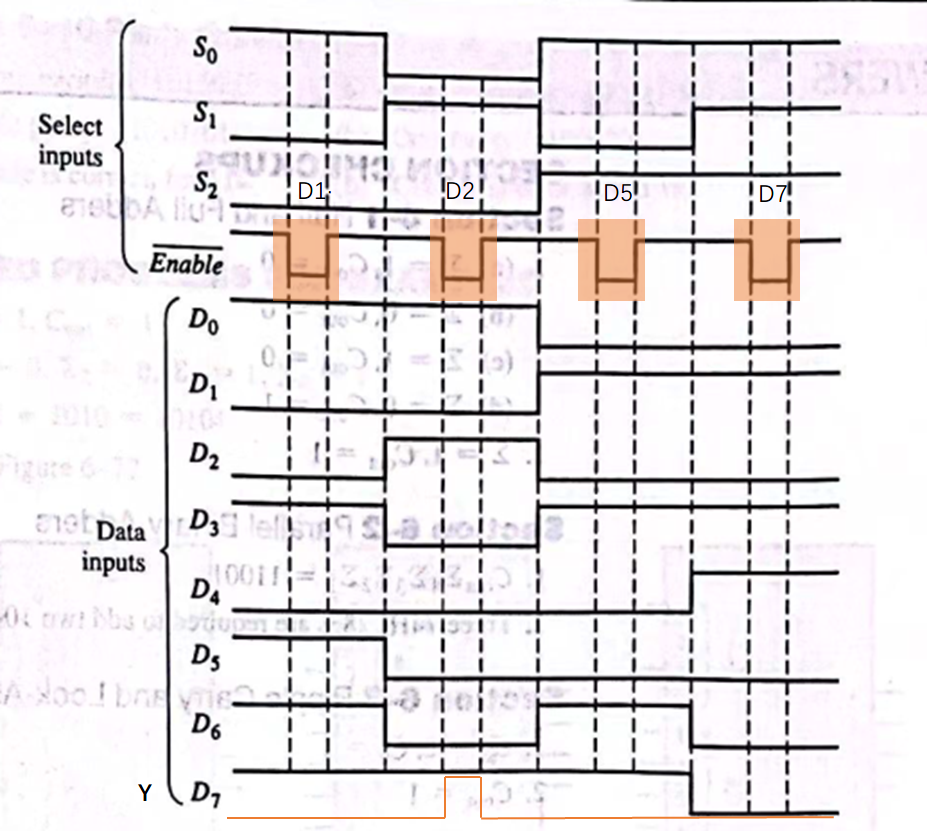
Demultiplexers (多路分用器)
A demultiplexer (DEMUX) reverses the multiplexing function, and it takes data from one line and distributes them to multiple output lines.
1-line-to-4-line demultiplexer
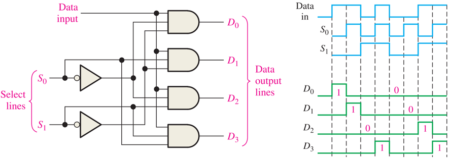
Decoders can be used in demultiplexing applications, where the input lines are used as the data select lines, and one of the enable inputs is used as the data input lines (other enable lines are active).
(译码器数据输入 作为 DEMUX 数据选择线; 译码器某一使能端 作为 DEMUX的数据数据输入.)
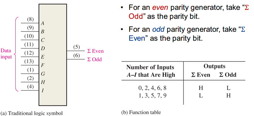
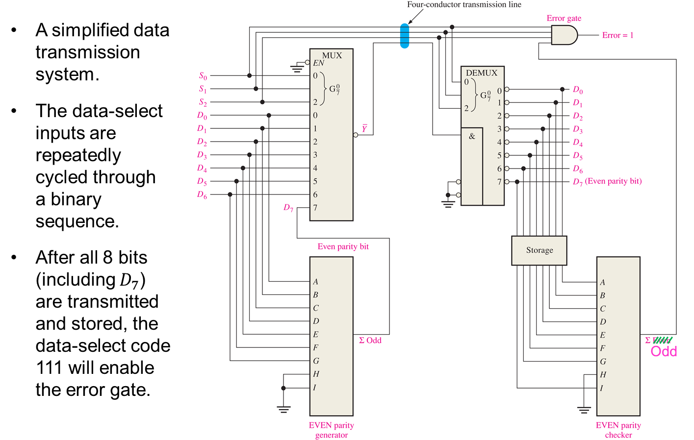
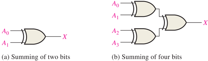
Parity Generators/Checkers (奇偶校验器)
Errors can occur as digital signals are transferred from one point to another.
In most digital systems, the probability of a single bit error is very small, and the likelihood of more than one error is even smaller.
An undetected error can cause serious problems.
Parity checking (奇偶校验) is the simplest method of error detection.
Recall that the basic idea is to attach a parity bit (奇偶校验位) to a group of bits to make the total number of 1s even (even parity, 偶校验) or odd (odd parity, 奇校验).
Note: Parity checking only can detect odd-bit errors.
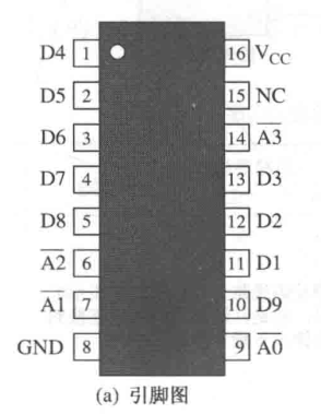
74HC280